Valve Logo
This standard is equivalent to the international standard ISO 5209-1977 "General Lined Valve Marking".
1 Subject content
This standard specifies the marking content and marking method that must be used and can be used optionally for general valves.
2 Marking
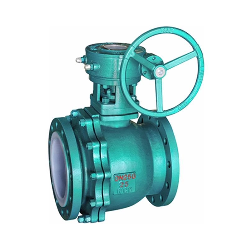
2.1 Marking of general valves
The marking items that must be used and can be used optionally for general valves are shown in the following table.
Item Mark Item Mark
1 Nominal diameter (DN) 11 Standard number
2 Nominal pressure (PN) 12 Melting furnace number
3 Material code of pressure-bearing parts 13 Material code of internal parts
4 Manufacturer name or trademark 14 Workstation number
5 Arrow of medium flow direction 15 Lining material code
6 Sealing ring (gasket) code 16 Quality and test mark
7 Limit temperature (℃) 17 Inspector's mark
8 Thread code 18 Year and month of manufacture
9 Limit pressure 19 Flow characteristics
10 Manufacturer number
Note: The nominal pressure cast mark value on the valve body is equal to 10 times the number of megapascals (MPa). When it is set below the nominal diameter value, it is not preceded by the code "PN".
2.2 Marking of handwheel rotation direction
If the handwheel size is large enough, an arrow indicating the closing direction of the valve or the word "off" should be set on the handwheel.
3 Marking method
3.1 Marking of valves with a nominal diameter greater than or equal to 50mm
3.1.1 Items 1 to 4 in the table are mandatory marks and should be marked on the valve body.
3.1.2 Items 5 and 6 in the table are mandatory marks only when there are such provisions in a certain type of valve standard. They should be marked on the valve body and flange respectively.
3.1.3 If there are no special provisions in the standards for various types of valves, items 7 to 19 in the table are marks that can be selected on demand. When necessary, they can be marked on the valve body or the nameplate.
3.2 Marking of valves with a nominal diameter less than 50mm
3.2.1 Items 1 to 4 in the table are mandatory marks. Whether to mark on the valve body or on the nameplate is determined by the product designer.
3.2.2 The markings of items 5 to 19 in the table shall be in accordance with the provisions of 3.1.2 and 3.1.3.
3.3 Additional markings
3.3.1 Any mark in the table may be added in different positions. For example, any mark on the valve body may also be repeated on the nameplate.
3.3.2 Any other mark may be added as long as the additional mark is not confused with the mark in the table. For example, product model, etc.
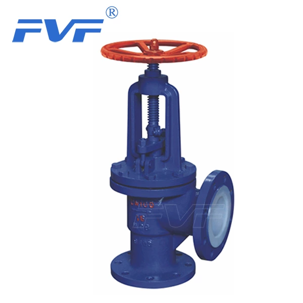
For the markings of pressure reducing valves, in addition to the markings in the above table, the markings on the valve body shall also include: a: date of manufacture; b: applicable medium; c: outlet pressure.
For steam traps, the markings may be placed on the valve body or on the nameplate as specified in the following table. The markings of steam traps (GB12249) must be used: product model; nominal diameter; nominal pressure; manufacturer name and trademark; medium flow direction; maximum working pressure; maximum working temperature. Optional markings: valve body material; maximum allowable pressure; maximum allowable temperature; maximum drain temperature; factory number and date.
Safety valve marking (GB12241)
Marks on the valve body: nominal diameter DN; valve body material; manufacturer name or trademark; when the size or pressure level of the inlet and outlet connection parts are equivalent, there should be an arrow indicating the flow direction of the medium
Marks on the plate: maximum allowable operating temperature designed for the valve (℃); set pressure (MPa); standard number based on the manufacturer's benchmark model; rated displacement coefficient or rated displacement for the benchmark medium; flow area (mm2); opening height (mm) percentage exceeding pressure
Identification of valves: painting
The outer surface of the valve should be painted before leaving the factory. The paint layer should be durable and meet US standards, and the markings should be clear and obvious.
1. Valve products are identified and painted according to the valve body material. The colors are as shown in the following table.
Valve body material Gray cast iron, malleable cast iron Ductile iron Carbon steel Acid-resistant steel, stainless steel Alloy steel
Identification paint color Black Silver Medium gray Sky blue Medium blue
Note: Acid-resistant steel and stainless steel are allowed to be unpainted, and copper alloy is not painted.
2. In order to indicate the material of the valve product sealing surface, identification paint should be applied to the transmission handwheel, handle, and wrench. The color is as specified in the following table. Sealing surface material Copper alloy Babbitt alloy Acid-resistant steel Stainless steel Nitriding steel Boronized steel Hard alloy Monel alloy Plastic Rubber Cast iron
Identification paint color Bright red Light yellow Sky blue Sky blue Sky blue Dark yellow Purple red Medium green Black
Note: (1) When the valve seat and the opening and closing parts sealing surface materials are different, the color of the material with lower hardness is applied.
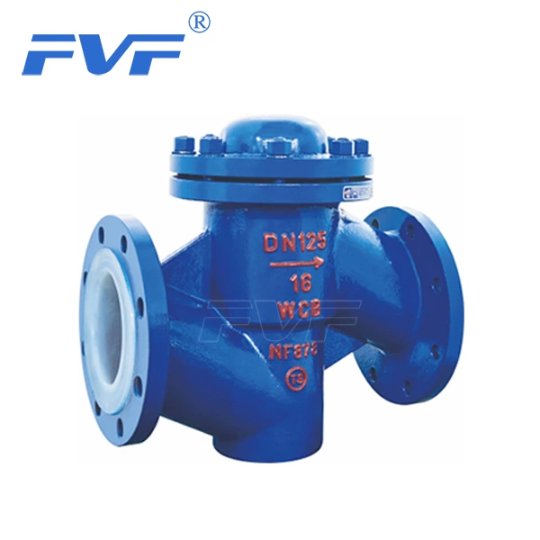
(2) Check valve, painted on the top of the valve cover: safety valve, pressure reducing valve, steam trap, painted on the valve cover or valve bonnet.
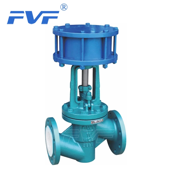
3. The paint color of the transmission mechanism shall comply with the following provisions:
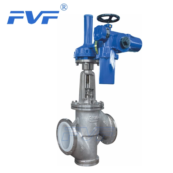
(1) Electric device: ordinary type is painted medium gray, three-in-one (outdoor, explosion-proof, anti-corrosion) type is painted blue.
(2) Other transmission mechanisms such as pneumatic, hydraulic, gear transmission, etc. are painted in the same color as the product.
4. The paint color can be changed according to the user's order requirements.