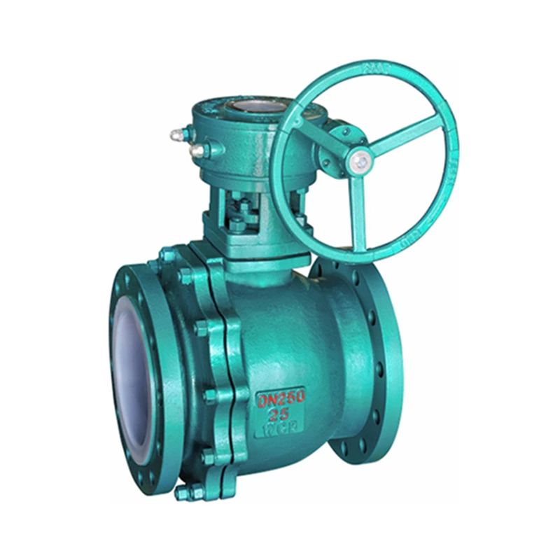
Valve Flow Rate, Fluid Resistance And Pressure Loss
When the fluid passes through Lined Valve, its fluid resistance loss is expressed as the fluid pressure drop before and after the valve.
1. Fluid resistance of valve components
The flow resistance coefficient of the valve depends on the size, structure and inner cavity shape of the valve product. It can be considered that each component in the valve body cavity can be regarded as a component system that generates resistance (fluid turning, expanding, shrinking, turning again, etc.). Therefore, the pressure loss in the valve is approximately equal to the sum of the pressure losses of each component of the valve.
It should be pointed out that the change of resistance of one component in the system will cause the change or redistribution of resistance in the entire system, that is, the medium flow affects each pipe section.
In order to evaluate the influence of each component on the valve resistance, some common valve component resistance data are quoted. These data reflect the relationship between the shape and size of the valve component and the fluid resistance.
(1) Sudden expansion will produce a large pressure loss. At this time, part of the fluid speed is consumed in the formation of vortex, fluid agitation and heat generation. The approximate relationship between the local resistance coefficient and the ratio of the cross-sectional area A1 of the pipe before expansion to the cross-sectional area A2 of the pipe after expansion can be expressed by formula (1-9) and formula (1-10); the resistance coefficient is shown in the table
(2) Gradual expansion When θ<40℃, the resistance coefficient of the gradually expanding circular tube is smaller than that of the sudden expansion, but when θ=50-90℃, the resistance coefficient is 15%-20% higher than that of the sudden expansion. The optimal expansion angle θ for gradual expansion: circular tube θ=5-6.5℃, square tube θ=7-8℃, rectangular tube 10-12℃.
(3) Sudden contraction (4) Gradual contraction (5) Smooth and uniform turning
(6) Angle turning Angle turning mainly occurs in forged valves because the medium channel of forged valves is processed by drilling. Sharp turns also occur in welded valves.
(7) Symmetrical tapered joints Symmetrical tapered joints are similar to valve necking channels.
2. Fluid resistance of valves
The flow resistance coefficient of valves varies with the type, model, size and structure of the valve.