Selection Guide For Several Common Valves
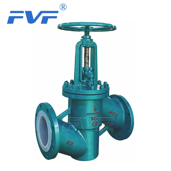
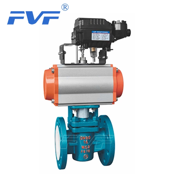
The valve stem axis of Lined Globe Valve is perpendicular to the valve seat sealing surface. The valve stem opening or closing stroke is relatively short, and has a very reliable cutting action, making this valve very suitable for cutting off or regulating and throttling the medium. Once the valve disc of the stop valve is in the open state, its valve seat and valve disc sealing surface will no longer be in contact, and it has a very reliable cutting action, making this valve very suitable for cutting off or regulating and throttling the medium.
Commonly used stop valves are as follows: 1) DC stop valve; In a DC or Y-shaped stop valve, the flow channel of the valve body is in an oblique line with the main flow channel, so that the degree of damage to the flow state is less than that of a conventional stop valve, and the pressure loss through the valve is also correspondingly smaller. 2) Angle stop valve; In an angle stop valve, the fluid only needs to change direction once, so that the pressure drop through this valve is smaller than that of a stop valve of conventional structure. 3) Plunger stop valve: This type of stop valve is a variant of a conventional stop valve. In this valve, the valve disc and valve seat are usually designed based on the plunger principle. The valve disc is polished into a plunger and connected to the valve stem. The seal is achieved by two elastic sealing rings on the plunger. The two elastic sealing rings are separated by a collar, and the sealing ring around the plunger is pressed firmly by the load applied to the valve cover by the valve cover nut. The elastic sealing ring can be replaced and can be made of various materials. The valve is mainly used for "opening" or "closing", but it is equipped with a special form of plunger or special collar, and can also be used to adjust the flow.
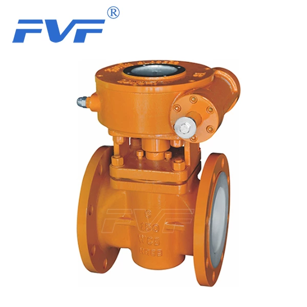
The gate valve is used to cut off the medium. When it is fully opened, the entire flow is straight through, and the pressure loss of the medium is minimized. The gate valve is usually suitable for working conditions that do not need to be opened and closed frequently, and keep the gate fully open or fully closed. It is not suitable for use as a regulator or throttling. For high-speed flowing media, the gate can cause vibration of the gate when it is partially opened, and the vibration may damage the sealing surface of the gate and the valve seat, and throttling will cause the gate to be eroded by the medium. In terms of structural form, the main difference is the form of the sealing element used. According to the form of sealing elements, gate valves are often divided into several different types, such as wedge gate valves, parallel gate valves, parallel double-disc gate valves, wedge double-disc gate valves, etc. The most commonly used forms are wedge gate valves and parallel gate valves.
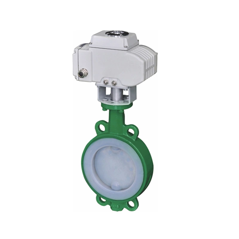
The butterfly plate of the butterfly valve is installed in the diameter direction of the pipeline. In the cylindrical channel of the butterfly valve body, the disc-shaped butterfly plate rotates around the axis, and the rotation angle is between 0° and 90°. When it rotates to 90°, the valve is fully open. The butterfly valve has a simple structure, small size, light weight, and is composed of only a few parts. Moreover, it can be quickly opened and closed by rotating 90°, which is simple to operate. At the same time, the valve has good fluid control characteristics. When the butterfly valve is in the fully open position, the thickness of the butterfly plate is the only resistance when the medium flows through the valve body. Therefore, the pressure drop generated by the valve is very small, so it has good flow control characteristics. Butterfly valves have two sealing types: elastic seal and metal seal. For elastic sealing valves, the sealing ring can be embedded in the valve body or attached to the periphery of the butterfly plate. Valves with metal seals generally have a longer life than valves with elastic seals, but it is difficult to achieve complete sealing. Metal seals can adapt to higher operating temperatures, while elastic seals have the defect of being limited by temperature.
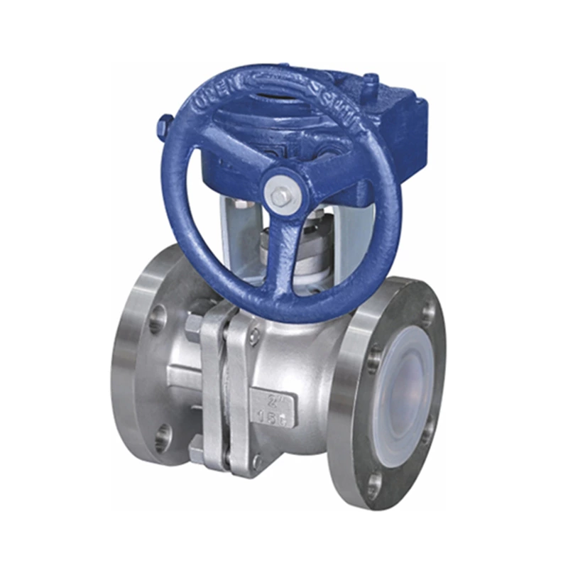
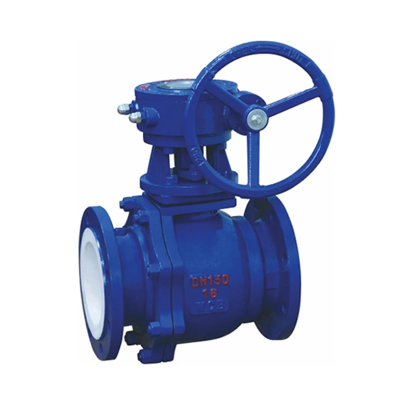
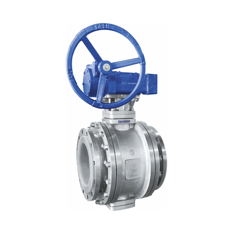
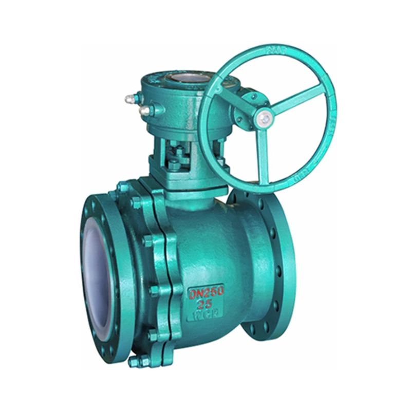
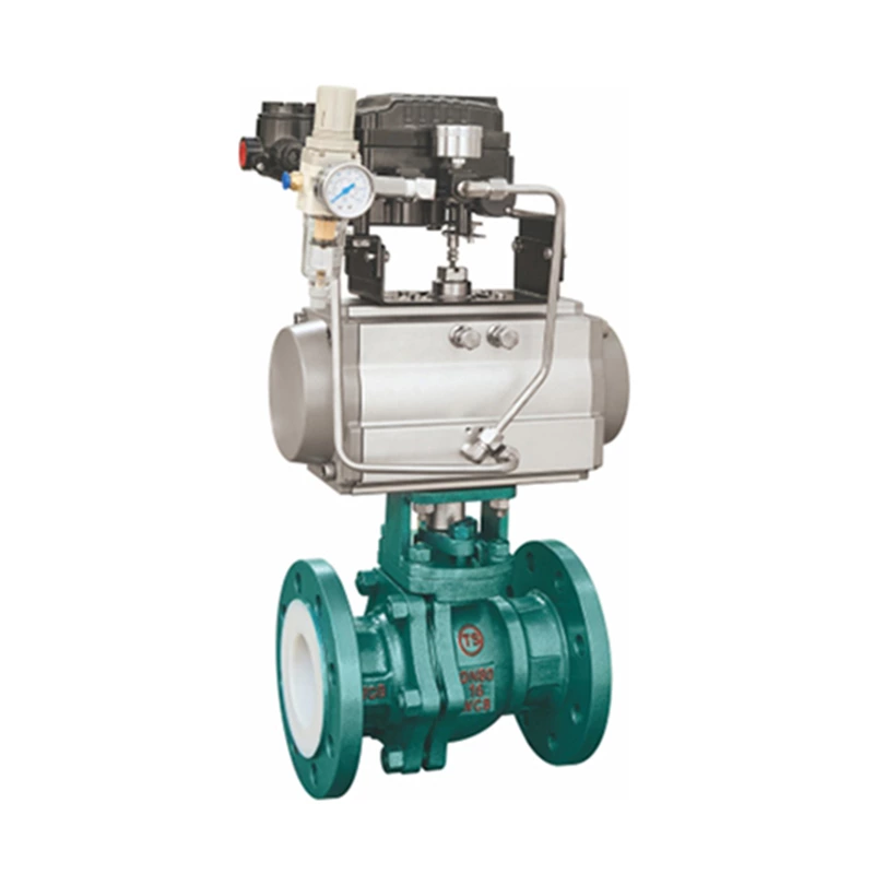
The ball valve evolved from the plug valve. It has the same 90-degree rotation lifting action, but the difference is that the plug body is a sphere with a circular through hole or channel passing through its axis. The ratio of the spherical surface to the channel opening should be such that when the ball rotates 90 degrees, the inlet and outlet should all present a spherical surface, thereby cutting off the flow.
The ball valve can be closed tightly with only a 90-degree rotation operation and a very small torque. The completely equal inner cavity of the valve body provides a very small resistance and straight flow channel for the medium. It is generally believed that the ball valve is most suitable for direct opening and closing, but recent developments have designed the ball valve to have the function of throttling and flow control. The main features of the ball valve are its compact structure, easy operation and maintenance, and it is suitable for general working media such as water, solvents, acids and natural gas, and also for media with harsh working conditions, such as oxygen, hydrogen peroxide, methane and ethylene. The ball valve body can be integral or combined.
Select the valve according to the method of preventing the medium from flowing back. The function of this type of valve is to allow the medium to flow in one direction only and prevent the medium from flowing in the opposite direction. Usually, this type of valve works automatically. Under the pressure of the fluid flowing in one direction, the valve disc opens; when the fluid flows in the opposite direction, the fluid pressure and the self-reclosing valve disc of the valve disc act on the valve seat to cut off the flow. Among them, the check valve belongs to this type of valve, which includes the swing check valve and the lifting check valve. The swing check valve has a hinge mechanism and a door-like valve disc freely resting on the inclined valve seat surface. In order to ensure that the valve disc can reach the appropriate position of the valve seat surface every time, the valve disc is designed in the hinge mechanism so that the valve disc has enough swing space and makes the valve disc truly and comprehensively contact the valve seat. The valve disc can be made entirely of metal, or it can be inlaid with leather, rubber, or a synthetic covering surface on the metal, depending on the performance requirements. When the swing check valve is fully opened, the fluid pressure is almost unimpeded, so the pressure drop through the valve is relatively small. The valve disc of the lift check valve is located on the valve seat sealing surface on the valve body. Except that the valve disc can be lifted and lowered freely, the rest of the valve is the same as the stop valve. The fluid pressure lifts the valve disc from the valve seat sealing surface, and the medium reflux causes the valve disc to fall back onto the valve seat and cut off the flow. Depending on the conditions of use, the valve disc can be a full metal structure or in the form of a rubber pad or rubber ring embedded in the valve disc frame. Like the stop valve, the passage of the fluid through the lift check valve is also narrow, so the pressure drop through the lift check valve is larger than that of the swing check valve, and the flow of the swing check valve is less restricted.