Selection And Precautions Of Valve Electric Devices
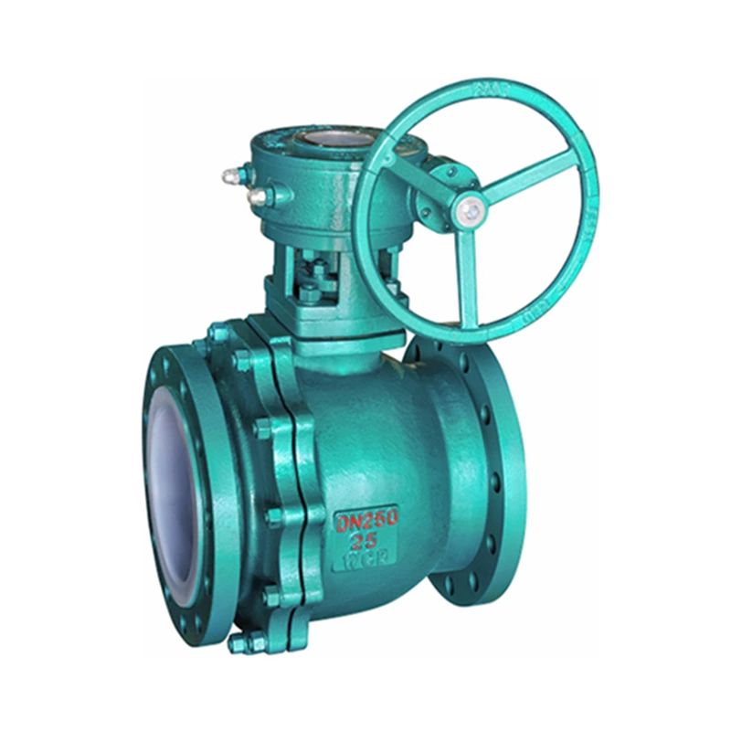
The electric device of Lined Valve is an indispensable device for realizing valve program control, automatic control and remote control. Its movement process can be controlled by the size of stroke, torque or axial thrust. Since the working characteristics and utilization rate of the valve electric device depend on the type of valve, the working specification of the device and the position of the valve on the pipeline or equipment, the correct selection of the valve electric device is crucial to prevent overload (working torque is higher than control torque). Generally, the basis for the correct selection of valve electric devices is as follows:
Operating torque: The operating torque is the most important parameter for selecting valve electric devices. The output torque of the electric device should be 1.2 to 1.5 times the maximum operating torque of the valve.
Operating thrust: There are two main structures of valve electric devices: one is not equipped with a thrust plate and directly outputs torque; the other is equipped with a thrust plate, and the output torque is converted into output thrust through the valve stem nut in the thrust plate.
Number of turns of the output shaft: The number of turns of the output shaft of the valve electric device is related to the nominal diameter of the valve, the valve stem pitch, and the number of thread heads. It should be calculated according to M=H/ZS (M is the total number of turns that the electric device should meet, H is the valve opening height, S is the valve stem transmission thread pitch, and Z is the number of valve stem thread heads).
Stem diameter: For multi-turn rising stem valves, if the maximum valve stem diameter allowed by the electric device cannot pass through the valve stem of the valve, it cannot be assembled into an electric valve. Therefore, the inner diameter of the hollow output shaft of the electric device must be larger than the outer diameter of the valve stem of the rising stem valve. For partial-turn valves and concealed stem valves in multi-turn valves, although the problem of the passage of the valve stem diameter does not need to be considered, the valve stem diameter and the size of the keyway should also be fully considered when selecting and matching, so that it can work normally after assembly.
Output speed: If the opening and closing speed of the valve is too fast, water hammer is likely to occur. Therefore, the appropriate opening and closing speed should be selected according to different use conditions. Valve electric devices have their special requirements, that is, they must be able to limit torque or axial force. Usually, the valve electric device adopts a torque-limiting coupling. When the specifications of the electric device are determined, its control torque is also determined. Generally, the motor will not be overloaded when running within a predetermined time. However, the following situations may cause overload: First, the power supply voltage is low, the required torque cannot be obtained, and the motor stops rotating; second, the torque limiting mechanism is incorrectly adjusted to be greater than the stopping torque, resulting in continuous excessive torque, causing the motor to stop rotating; third, intermittent use, the heat accumulation generated exceeds the allowable temperature rise value of the motor; fourth, for some reason, the torque limiting mechanism circuit fails, causing excessive torque; fifth, the use environment temperature is too high, which relatively reduces the thermal capacity of the motor.
In the past, the way to protect the motor was to use fuses, overcurrent relays, thermal relays, thermostats, etc., but these methods have their own advantages and disadvantages. There is no absolutely reliable protection method for variable load equipment such as electric devices. Therefore, various combinations must be adopted, which can be summarized into two types: one is to judge the increase or decrease of the motor input current; the other is to judge the heating condition of the motor itself. Both methods must consider the time margin given by the motor thermal capacity.
Usually, the basic overload protection method is: for overload protection of continuous operation or inching operation of the motor, a thermostat is used; for protection of motor stall, a thermal relay is used; for short circuit accidents, a fuse or overcurrent relay is used.