Pressure-sealed Valve Leak-proofing Technology For Thermal Power Plants
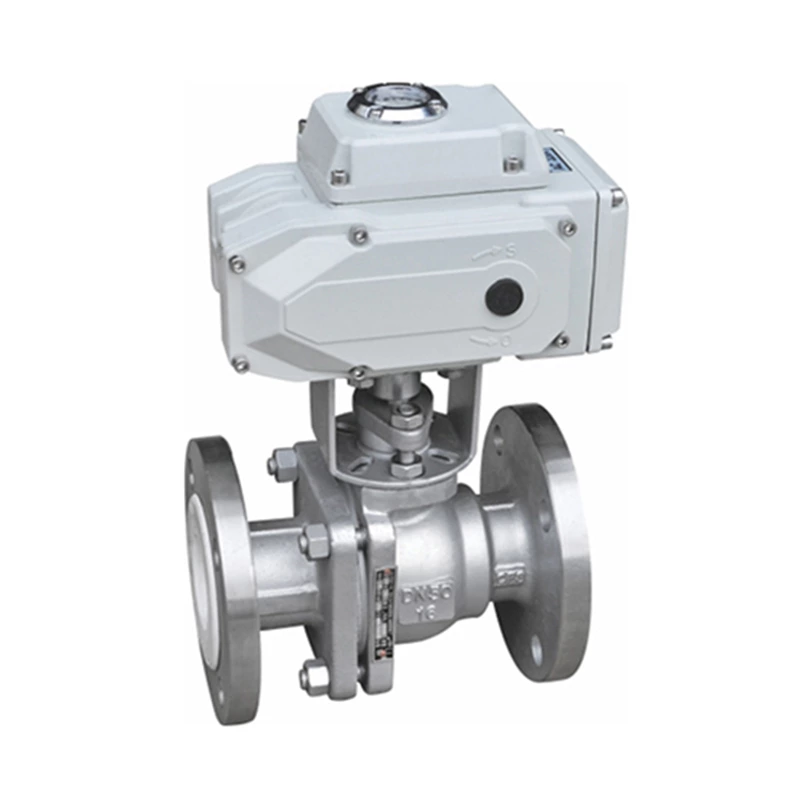
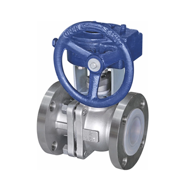
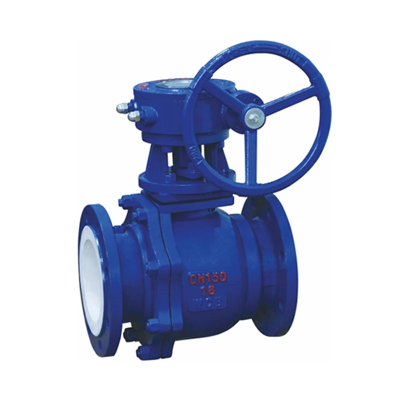
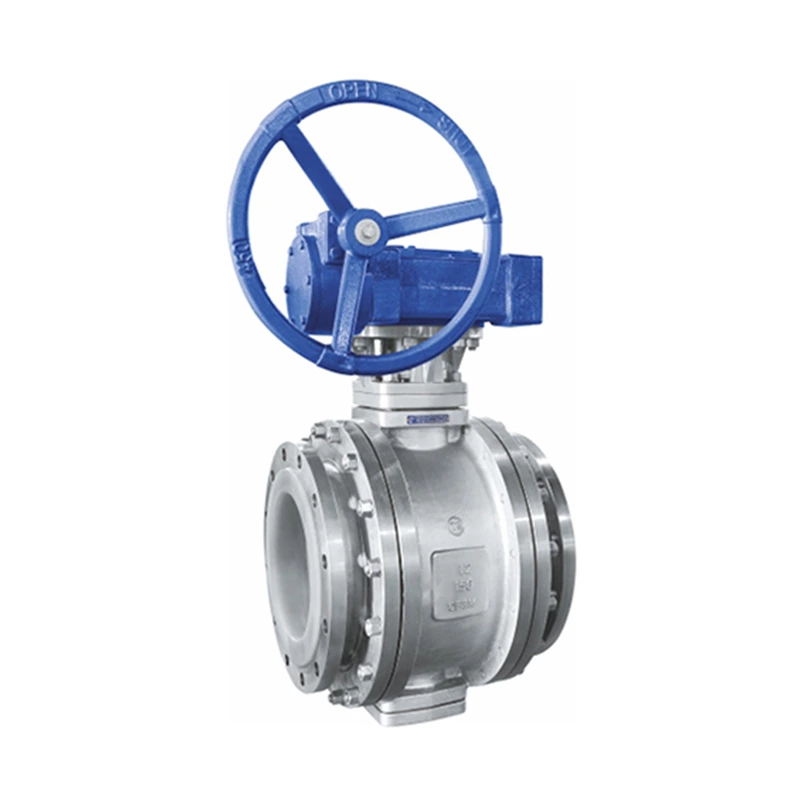
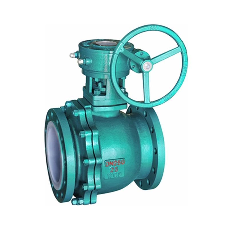
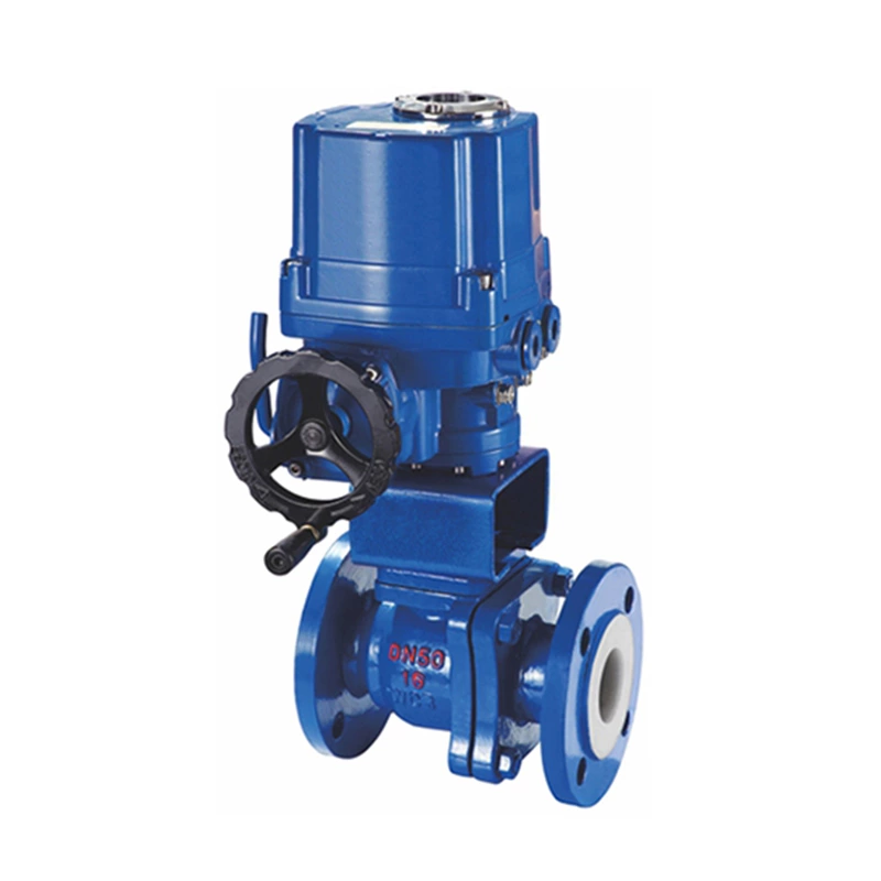
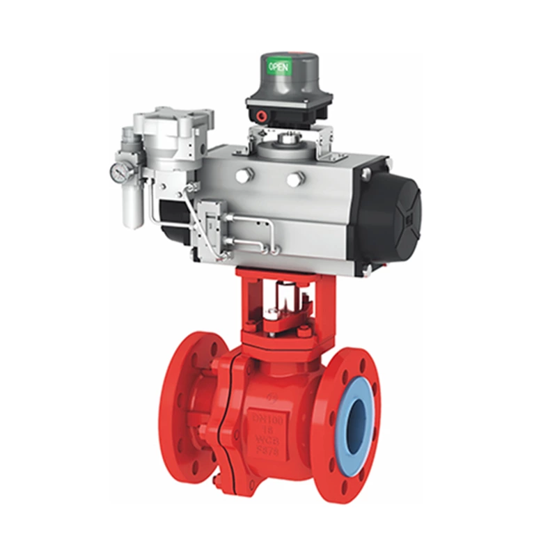
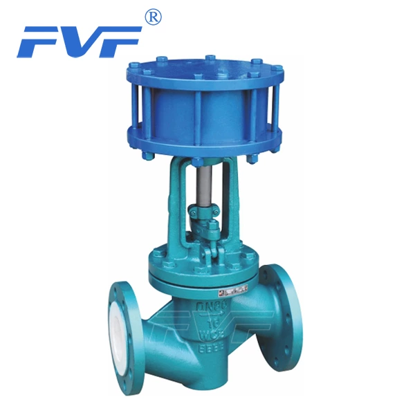
Lined Valve is mainly used to control the operation of fluid media in various equipment and their pipelines. Valve leakage often occurs on the packing, flange seal and valve body. Long-term leakage of the valve can cause erosion of the valve stem and flange sealing surface, and eventually the valve can be scrapped. In addition, the loss of the medium fluid increases the consumption of the power plant, increases costs, and reduces economic benefits. If the medium fluid is toxic, flammable, explosive, corrosive, etc. and leaks out, it is easy to cause poisoning, fire, explosion and other casualties and accelerate the corrosion rate of plant equipment, shorten its service life, and pollute the surrounding environment in serious cases, destroy power production, and harm people's health. The existence of leakage seriously threatens production safety and increases the number of unplanned shutdown accidents in power plants. The following introduces some causes of valve leakage and plugging methods as well as valve repair and maintenance methods for reference.
2 Forms and factors of valve leakage
2.1 Leakage and causes of valve packing
During the operation and use of the valve, there is relative movement between the valve stem and the packing, which includes rotation and axial movement. As the number of switches increases, the number of relative movements also increases, and the temperature, pressure and characteristics of the fluid medium are also affected. The valve packing is the most prone to leakage. It is caused by the gradual weakening of the packing contact pressure, the aging of the packing itself, and the loss of elasticity. At this time, the pressure medium will leak out along the contact gap between the packing and the valve stem. For a long time, part of the packing will be blown away and the valve stem will be washed out of the groove, thereby expanding the leakage.
2.2 Flange leakage
The flange seal of the valve mainly relies on the pre-tightening force of the connecting bolts to achieve sufficient sealing pressure ratio through the gasket to prevent the leakage of the sealed pressure fluid medium. There are many reasons for its leakage. The compression force of the sealing gasket is insufficient, the roughness of the joint surface does not meet the requirements, the deformation of the gasket and the mechanical vibration will cause the sealing gasket and the flange joint surface to be loose and leak. In addition, the deformation or elongation of the bolts, the aging of the gasket, the decrease in resilience, and the cracking will also cause the flange surface to be loosely sealed and leak. There are also human factors that cannot be ignored in flange leakage, such as the sealing gasket is installed skewed, which makes the local sealing ratio insufficient and the tightening force excessive, exceeding the design limit of the sealing gasket, and the uneven force during the flange tightening process or the deviation of the center line of the two flanges, resulting in false tightening, which are prone to leakage.
2.3 Leakage and causes of valve body
The main reason for the leakage of the valve body is due to casting or forging defects in the valve production process, such as sand holes, pores, cracks, etc., and the scouring and cavitation of fluid media are also common factors causing valve body leakage.
3 Principles and advantages of plugging with pressure
3.1 Principle of plugging with pressure
The principle of plugging with pressure is based on the sealing mechanism of solid sealing materials under dynamic conditions of liquid media. The method is to install special equipment at the leakage site, use the chamber formed between the sealing site and the special equipment, and use a special high-pressure injection tool to inject the sealant into the chamber and fill the entire chamber space, so that the extrusion force of the sealant is balanced with the pressure of the leaking medium, and a new sealing structure is established to block the leakage pores and channels to block the leakage of the medium.
3.2 Advantages of plugging leaks under pressure
(1) No need to shut down or isolate the system.
(2) No need to depressurize the system.
(3) Save a lot of energy and manpower.
(4) Greatly reduce the power loss caused by equipment isolation or shutdown.
(5) Reduce social and economic losses.
4 Introduction to several common leak plugging methods under pressure
According to the specific conditions of the power plant production site, general leaks can be eliminated by replacing valves, replacing valve packing, replacing flange gaskets or welding holes.
However, for valves in production and operation, if they cannot be isolated, corresponding technical means must be taken to eliminate the leak to ensure the normal operation of the unit's safe production.
4.1 Treatment of leaks in the packing chamber of power plant valves under pressure
The use of injection-type plugging technology under pressure is currently a relatively safe and reliable technical means. It uses special fixtures and hydraulic injection tools to inject sealants into the sealed cavity formed by the fixture and the outer surface of the leaking part to quickly make up for various complex leakage defects. Under the condition that the injection pressure is greater than the leakage medium pressure, the leakage is forcibly stopped, and the injection itself changes from a plastic to an elastomer in a short time, forming an elastic sealing structure and maintaining a certain working sealing pressure ratio, so as to achieve the purpose of resealing. At present, the sealing injections produced and used at home and abroad are roughly divided into two categories: one is a heat-curing sealing injection, which can only change from a plastic to an elastomer when it reaches a certain temperature, and is solid at room temperature; the other is a non-heat-curing sealing injection, which is suitable for dynamic sealing operation requirements at room temperature, low temperature and high temperature. This type of sealing injection is mostly made into a rod-shaped solid or a two-component greasy material. After it is installed in a high-pressure injection gun, it has good injection processability and filling properties under a certain pressure, and does not lose the valve switching function. The following are two common methods:
(1) When the wall thickness of the valve stuffing box is greater than about 8mm, when the injection-type pressure plugging is used to eliminate defects under dynamic conditions, the injection hole can be directly opened on the wall of the valve stuffing box. The sealing cavity is the valve stuffing box itself. The role of the sealing injection injected into the valve stuffing box is the same as that of the stuffing. First, use a drill with a diameter of 10.5mm or 8.7mm to make a hole at the appropriate position of the outer wall of the valve stuffing box. The hole cannot be drilled through, leaving about 1-3mm. Remove the drill bit and tap with an M12 or M10 tap. After tapping, screw on the special plug valve for injection and put it in the open position. Use a long-rod drill with a diameter of 3mm to drill through the remaining valve stuffing box wall. At this time, the leaked medium will spray out along the direction of the drill row. In order to prevent high temperature, high pressure, toxic or corrosive media from spraying out and injuring people during drilling, a baffle can be used before drilling a small hole. First, use a drill to drill a hole with a diameter of 5mm on the baffle so that it can fit over the long drill bit. With the baffle, there will be no danger in drilling the remaining wall thickness. After drilling through the small hole, remove the drill bit, screw the special plug valve for injection to the closed position, cut off the medium and connect the high-pressure injection gun to inject the sealing injection. If the medium pressure in the valve stuffing box is low, you can also use a long drill bit with a diameter of 3mm to drill through the small hole directly, and then perform the sealing injection operation.
In June 2003, the self-sealing gland of the electric main steam valve of the 3# unit of Panzhihua Iron and Steel Power Plant was solved by this plugging technology, avoiding the problem of having to shut down the machine to solve it.
(2) For valves with thinner stuffing box walls, auxiliary clamps can be used for dynamic sealing operations. The auxiliary clamp is only to make up for the lack of thickness of the valve stuffing box wall. It is equivalent to a special joint fixed to the outer wall of the valve stuffing box for connecting a high-pressure injection gun. The mechanical processing method of the clamp is difficult to obtain an ideal local fitting surface. If conditions permit, the outer wall of the valve stuffing box can be properly repaired to make it fit better with the auxiliary clamp. If the outer wall of the packing of the leaking valve is complex in shape or the trimming conditions do not allow, an asbestos rubber sheet or rubber sheet can be placed at the bottom of the auxiliary clamp, and the clamp bolts can be tightened so that the rubber sheet underneath can well block the gap in the fitting surface. The auxiliary fixture should have a threaded patch that matches the injection plug valve. Then the operation of the stuffing box with the same wall thickness should be the same. After the entire sealing operation is completed, do not open and close the valve immediately. Wait until the sealing injection is solidified before it can be put into normal use.
In mid-November 2002, the balance valve flange of the high-pressure heater inlet gate of Panzhihua Iron and Steel Power Plant leaked. Since the stuffing box wall of the valve was thin, the auxiliary fixture was made for dynamic sealing, which solved the leakage problem of the valve.
4.2 Pressure plugging treatment of valve flange leakage in power plants
4.2.1 Copper wire containment method
It is suitable for pressure plugging with small gaps between the two flanges, uniform gaps, and low leakage medium pressure. The special injection joints for bolts can be directly placed on the removed bolts, generally not less than two.
When installing the injection joint, one nut should be loosened, the injection joint should be installed, the nut should be quickly re-tightened, and then the other injection joint should be installed. The nuts of the required joints should not be loosened at the same time, so as to avoid a significant decrease in the sealing pressure on the gasket, an increase in leakage, and even the leakage medium blowing the gasket away, resulting in irreparable consequences. If the original leakage is large, a G-shaped clamp can be used to maintain the balance of the sealing pressure. After installing the injection bolt, use a tool to embed a copper wire with a diameter or slightly smaller than the leakage flange gap into the flange gap, and at the same time punch out the lip of the outer edge of the flange so that the copper wire is fixed in the flange gap, thus forming a new sealing cavity. Then the high-pressure injection gun can be connected for dynamic sealing operations. The injection direction should be carried out in sequence from the opposite side of the leakage point, and the end point should be near the leakage point.
In June 2003, the vertical flange surface leakage of the low-pressure connecting pipe of the No. 1 unit of the Panzhihua Iron and Steel Power Plant was solved by using this plugging technology to solve the leakage problem of the connecting pipe flange surface, avoiding a shutdown accident.
4.2.2 Steel belt containment method
When the gap between the two flanges is slightly larger and does not exceed 8mm, and the medium pressure is less than 2.5MPa, the steel belt containment method can be used for dynamic sealing. It has high requirements for the coaxiality of the two flanges, but not high requirements for the uniformity of the flange gap. The steel belt is generally selected with a thickness of 1.5--3.0mm and a width of 20--30mm. It can be welded or riveted during production. Transition gaskets need to be added under the two joints. The number of injection joints to be installed is determined according to the flange size. When installing the steel belt, the steel belt should be located on the gap between the two flanges, the connecting bolts should be slightly tightened a few times, and then the two transition gaskets should be added to completely cover the flange gap. Continue to tighten the bolts to finally form a complete sealing cavity. At this time, dynamic sealing operations can be performed.
4.2.3 Flange convex clamp plugging method
When the gap of the leaking flange is greater than 8mm and the medium pressure is greater than 2.5MPa, from the perspective of safety and reliability, a flange clamp with precise processing dimensions, good overall sealing performance and high pressure resistance should be designed and manufactured. It has a high success rate of dynamic sealing operations and is a widely used sealing technology. Before the operation, a plug valve should be installed on the fixture, and the plug valve should be in the open state. The operator should stand at the upwind. If the leakage pressure or flow is large, the leaking medium can be blown to one side with compressed air, or a long rod can be connected to the fixture to prevent the operator from contacting the leaking medium. During installation, the injection hole of the fixture should be in the middle of the two flange connection bolts, and ensure that there is an injection hole near the leak. Do not align the injection hole with the bolt to avoid increasing the resistance of the injection. After the fixture bolts are tightened, the maximum contact gap between the fixture and the flange should not exceed 0.5mm. The injection should be injected from the farthest point from the leak point, gradually approaching the leak until the leak stops. This method can also be used for pressure plugging of pipelines.
This plugging method is widely used in the daily maintenance of units #1, #2, and #3 of Panzhihua Iron and Steel Power Plant. It is a plugging method that must be mastered by pipe and valve maintenance professionals. For example, in 2003, the flanges of the primary and secondary valves of the feed pump positive warm return water drain of units #1 and #2 leaked; in February 2003, the flange in front of the 70% electric isolation valve from the auxiliary steam of unit #2 to the deaerator drain leaked; in March 2003, the flange of the inlet of the high-pressure heater of unit #1 leaked, etc.
4.3 Pressure plugging treatment of valve body leakage in power plants
The leakage treatment of the valve body can be applied to the leakage treatment of pipelines. There are two methods:
4.3.1 Adhesive method
It is a method of plugging leakage under pressure using the special properties of adhesives. For the pressure medium and the sand hole with small leakage, the metal luster can be polished around the leakage point first, and then the taper pin can be aimed at the leakage point and driven in with appropriate force to significantly reduce the leakage or temporarily block it. Taking advantage of the fast curing speed of the adhesive, the adhesive is applied around the pin in time to form a new solid sealing structure to stop the leakage. For defects with high medium pressure and large leakage, the top pressure tool can be used for sealing. During operation, the top pressure mechanism is fixed to one side of the valve, and the top pressure screw is pressed at high speed so that the axial direction of the top pressure screw is directly opposite to the leakage point. The top pressure screw is rotated, and the rivet at the end of the top pressure screw is tightly pressed on the leakage part to force the leakage to stop.
If the top of the rivet is smaller than the leakage point, a soft metal sheet can be placed under the rivet. After the leakage stops, clean the metal surface around the leakage point in time, remove the rust and oil, and apply the prepared adhesive around it. After the adhesive is fully cured, remove the fixing screws of the top pressure screw and the rivet, remove the top pressure mechanism, and in order to ensure its pressure resistance effect, the treated leakage part can be reinforced with glass cloth.
4.3.2 Welding method
a) When the leakage medium pressure of the valve body is low and the leakage volume is small, a nut with an inner diameter more than twice that of the leakage point can be used to allow the leakage medium to flow out of the nut, weld the nut to the valve body, and then match it with a bolt of the same specification as the nut, place a rubber pad or asbestos pad at the bottom of the nut, wrap the top of the bolt with raw tape and screw it into the nut to achieve the purpose of preventing leakage. For valve bodies with high leakage medium pressure and large leakage volume, the drainage welding method can be used. First, use an iron plate with a round hole in the middle, weld an isolation valve with a diameter equivalent to the round hole to the round hole of the iron plate, open the isolation valve, align the center hole of the iron plate with the leakage point and fit it to the valve body, and let the leakage medium flow out through the center hole of the iron plate and the isolation valve. If the fitting surface is not good, a rubber or asbestos pad can be placed on the fitting surface, and then the iron plate and the valve body are welded well, and then the isolation valve can be closed to achieve the purpose of resealing.
b) When the leakage medium of the valve body is high temperature and high pressure, but the valve has a large outer size and the leakage is not large, welding can also be used. First, directly weld all the gaps related to the leakage point on the valve body (do not weld the leakage point), and then use a pipe that meets the working conditions (working temperature and pressure) and the length depends on the site environment (generally about 200mm), and its diameter should be larger than the leakage point. Weld a valve that is compatible with the pipe to one end of the pipe and fully open the valve, then align the other end of the pipe with the leakage point and weld it. Close the valve to stop the leakage.
4.4 Universal plugging method
No matter which part of the valve leaks, if the above methods are difficult to operate, you can also use the "wrapping method": use a plate (pipe) that meets the working conditions to make a box that can wrap the entire valve or the valve body with a leakage point, and weld it to the valve so that it can wrap the leakage point. If there are difficulties in welding the box, you can open a hole in the box and leave it until the end. Method b) in the welding method: the method of adding an exhaust valve can easily seal the welding. This welding method has been used many times in the main steam duct drainage of Panzhihua Iron and Steel Power Plant #1 unit, the secondary door of the main steam duct bypass of #3 unit, and the drainage system of the high-pressure heater of units 1#, 2#, and 3#, and has achieved satisfactory success. This plugging method is the most commonly used and most effective method in the daily maintenance of units #1, #2, and #3 of Panzhihua Iron and Steel Power Plant, and it is also a plugging method that must be mastered by pipe and valve maintenance professionals.
5 Conclusion
There are other components that need to be plugged under pressure at the production site of the power plant. If we can master some basic plugging knowledge, it will be of great help to improve the economic efficiency of the power plant. The direct economic loss of a 100MW unit in our plant is more than RMB 300,000 when it is started and stopped once. Therefore, we can successfully plug the leaks at the on-site leaks under pressure and reduce the number of unplanned shutdowns. The benefits are significant. In summary:
(1) Plugging leaks under pressure is a kind of emergency repair work. The leaks treated by plugging leaks under pressure are a temporary treatment measure with certain limitations and timeliness. Under certain conditions,Under such circumstances, the leaking part should be thoroughly inspected. The fundamental way to eliminate the "running, bubbling, dripping and leaking" phenomenon on site and improve the health level of equipment operation is to rely on the rationality of planned maintenance and improve the process of equipment maintenance and maintenance.
(2) The working environment of pressure plugging is harsh, the operation time is long, the labor intensity is high, there are many uncertain factors in the operation, and the operation risk is high. Safety preparation before work is very important. The risk analysis before operation must be sufficient and the implementation of safety measures must be in place.
(3) Pressure plugging is a highly professional technology, which requires the on-site response ability of the operator, the mastery of mechanical professional knowledge and the use of special tools for pressure plugging. Due to the high requirements for operators and special equipment, this technology is difficult to promote in thermal power plants. At present, the on-site pressure plugging work is completed by some professional companies.
(4) Pressure plugging is a new technology, and it still has a process of continuous improvement and perfection. It has its own limitations and scope of application. Pressure plugging cannot solve all leakage problems and is still in the stage of exploration and improvement.