How To Choose Fluorine-lined Stop Valve?
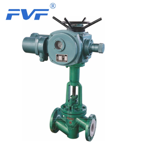
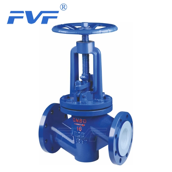
Lined Globe Valve is a forced sealing valve, so when the valve is closed, pressure must be applied to the valve disc to force the sealing surface to not leak. When the medium enters the valve from below the valve disc, the resistance that the operating force needs to overcome is the friction between the valve stem and the packing and the thrust generated by the pressure of the medium.
The force to close the valve is greater than the force to open the valve, so the diameter of the valve stem should be larger, otherwise the valve stem will bend. Since the emergence of self-sealing valves, the medium flow direction of the stop valve has changed to enter the valve cavity from above the valve disc. At this time, under the effect of the medium pressure, the force to close the valve is small.
The force to open the valve is large, and the diameter of the valve stem can be reduced accordingly. At the same time, under the effect of the medium, this type of valve is also tighter. my country's valve "three-in-one" has stipulated that the flow direction of the stop valve should be from top to bottom.
When the fluorine-lined stop valve is open, when the opening height of the valve disc is 25%~30% of the nominal diameter, the flow rate has reached a large value, indicating that the valve has reached the full open position. Therefore, the fully open position of the stop valve should be determined by the stroke of the valve disc.
Many fluorine-lined stop valves use T-shaped valve bodies, which can be installed on straight-through production lines. Logistics enter the center of the valve through the inlet, where the valve body changes its direction of movement by 90 degrees and passes through the valve seat, and then another 90° turn and flows out of the valve. Let's learn how to choose a fluorine-lined stop valve manufacturer!
The movement direction of the fluorine-lined stop valve varies depending on the manufacturer and operating conditions, but in most cases, the movement direction is almost always below the valve core. If the signal is placed in the flow direction, it has a certain resistance, but it is enough to overcome. Relative to the downstream of the valve body, the valve is relatively easy to close, and the fluid pressure and flow rate do not change much. In addition, the movement below the valve body is easily opened by the fluid pressing the bottom of the valve body.
The manual stop valve can be adjusted to a percentage, linear or quick-opening movement characteristic. As explained in detail in Section 2.2, the movement characteristic is expressed by the expected flow rate (movement coefficient CV) at the position of the valve. In this way, for a certain movement characteristic, the user can determine the flow rate based on the linear position of the handwheel.
When the valve head is in the saving position (between full open and full closed), the flow moves to the movable opening of the valve seat through the pressure drop. In the saving position, the head of the valve core slightly enters the valve seat ring, providing corresponding movement in a special position with specified movement characteristics. After retreating from the valve seat, a larger flow rate can be achieved. After further extending to the valve seat, the flow rate will become smaller.
