How Much Do You Know About The Commonly Used Valves And Principles In Installation Projects
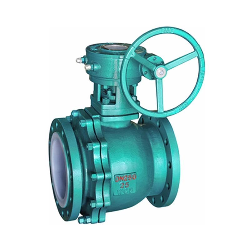
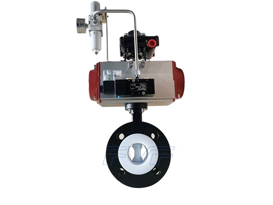
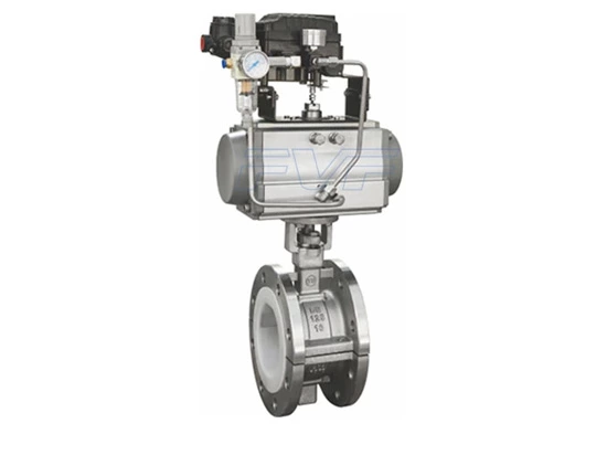
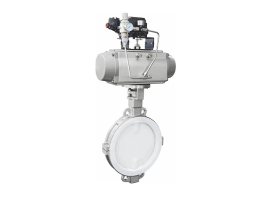
1. Lined Valve
The gate valve, also called the gate valve, is a commonly used valve. Its closing principle is that the gate sealing surface and the valve seat sealing surface are highly smooth, flat and consistent, fit each other, can prevent the medium from flowing through, and rely on the top mold, spring or gate mold shape to enhance the sealing effect. It mainly plays a cutting role in the pipeline.
Its advantages are: small fluid resistance, easy opening and closing, can be used in the case of bidirectional flow of the medium, no directionality, the sealing surface is not easy to erode when fully opened, short structure length, not only suitable for small valves, but also suitable for large valves.
Gate valves are divided into two categories according to the valve stem thread, one is the rising stem type, and the other is the concealed stem type. According to the gate structure, there are also two categories, one is parallel and the other is pattern.
2. Stop valve
The stop valve, also called the stop valve, is a commonly used valve. It is popular because of the small friction between the sealing surfaces during the opening and closing process, it is relatively durable, the opening height is not large, it is easy to manufacture and maintain, and it is not only suitable for medium and low pressure, but also for high pressure.
Its closing principle is to rely on the valve stem pressure to make the valve disc sealing surface and the valve seat sealing surface fit tightly to prevent the flow of the medium.
The stop valve only allows the medium to flow in one direction and has directionality when installed. Its structural length is greater than that of the gate valve, and the fluid resistance is large. When it is in long-term operation, the sealing reliability is not strong.
Stop valves are divided into three categories: straight-through, right-angle and direct current oblique stop valves.
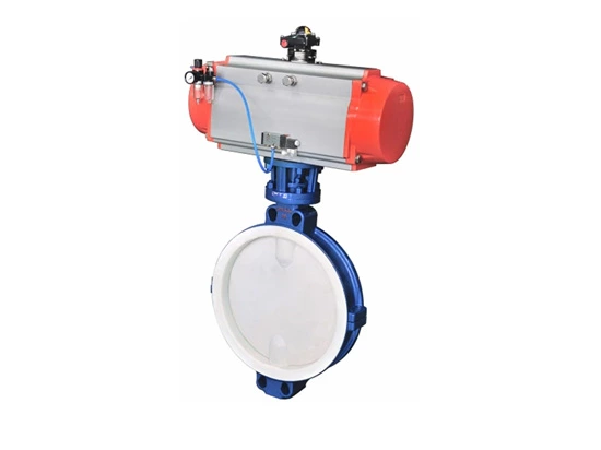
3. Butterfly valve
Butterfly valve is also called butterfly valve. As the name suggests, its key component is like a butterfly facing the wind and rotating freely.
The valve disc of the butterfly valve is a disc that rotates around an axis in the valve seat. The size of the rotation angle is the opening and closing degree of the valve.
The butterfly valve is lightweight, saves materials more than other valves, has a simple structure, opens and closes quickly, can be used for cutting off and throttling, has low fluid resistance, and is labor-saving to operate. The butterfly valve can be made into a large diameter. Where butterfly valves can be used, try not to use gate valves, because butterfly valves are more economical than gate valves and have good adjustability. At present, butterfly valves are widely used in hot water pipelines.
4. Ball valve
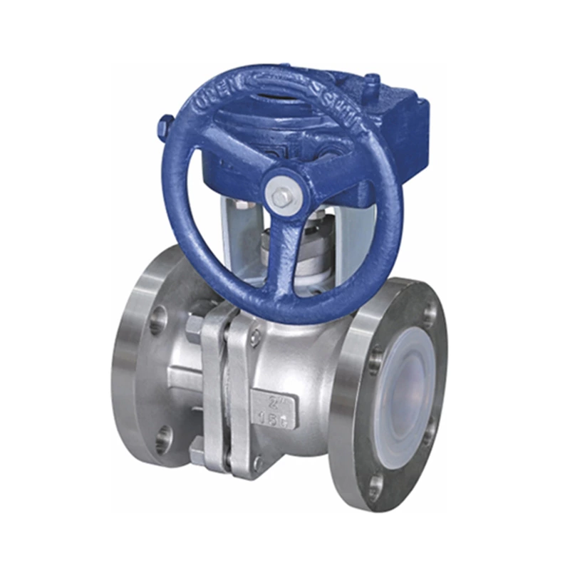
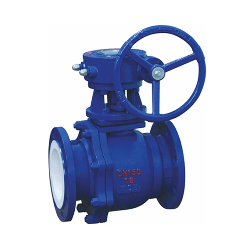
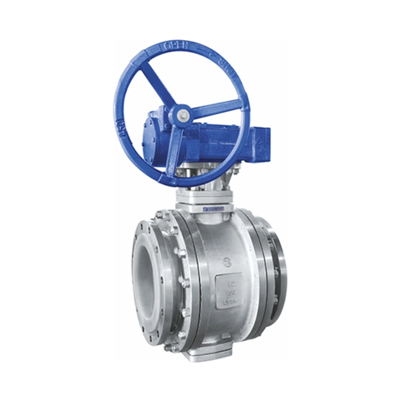
The working principle of the ball valve is to make the valve unblocked or blocked by rotating the valve ring. The ball valve is light and small in size, can be made into a large diameter, has reliable sealing, simple structure, and is easy to maintain. The sealing surface and the spherical surface are often in a closed state and are not easily eroded by the medium. It is widely used in various industries.
Ball valves are divided into two categories, one is the floating ball type, and the other is the fixed ball type.
5. Plug valve
The plug valve relies on the plug body to rotate around the center line of the valve body to achieve the purpose of opening and closing. Its function is to cut off, divide and change the flow direction of the medium. The structure is simple, the size is small, and it only needs to be rotated 90 degrees when operated. The fluid resistance is not large. Its disadvantages are that it is laborious to open and close, the sealing surface is easy to wear, it is easy to get stuck at high temperature, and it is not suitable for regulating flow.
Plug valve, also known as plug, cock, and rotary valve. There are many types of it, including straight-through type, three-way type and four-way type.
6. Check valve
The check valve is a valve that automatically opens and closes by the power of the fluid itself. Its function is to prevent the medium from flowing back. It has many names, such as non-return valve, one-way valve, and one-way valve. It can be divided into two categories according to the structure.
(1) Lifting type: The valve disc moves along the vertical center line of the valve body. There are two types of this type of check valve: one is horizontal, installed in horizontal pipes, and the valve body shape is similar to that of a stop valve; the other is vertical, installed in vertical pipes.
(2) Swing type: The valve disc rotates around the pin outside the seat. This type of valve is divided into single-disc, double-disc and multi-disc, but the principle is the same.
The water suction bottom valve of the water pump suction pipe is a deformation of the check valve. Its structure is the same as the above two types of check valves, except that its lower end is open to allow water to enter.
7. Pressure reducing valve
The pressure reducing valve is an automatic valve that reduces the medium pressure to a certain value. Generally, the pressure after the valve is less than 50% of the pressure before the valve. There are many types of pressure reducing valves, mainly piston type and spring diaphragm type.
The piston type pressure reducing valve is a valve that reduces pressure through the action of the piston. The spring diaphragm type pressure reducing valve relies on springs and diaphragms to balance the pressure.
8. Steam trap
The steam trap is also called steam-blocking drain valve, steam-water valve, steam trap, water return box, water return gate, etc. Its function is to automatically discharge the continuously generated condensate without letting the steam out.
There are many types of steam traps, including float type, ball float type, bell float type, pulse type, thermal dynamic type, and thermal expansion type. Commonly used ones are float type, bell float type, and thermal dynamic type.
(1) Float type steam trap, float type steam trap, mainly consists of valve, shaft, conduit, float and shell.
When condensate in the equipment or pipeline enters the steam trap under the pressure of steam, and gradually increases until it is close to filling the float, the weight of the float exceeds the buoyancy and sinks downward, causing the throttle valve to open. In this way, the condensate in the cylinder is discharged through the conduit and valve under the action of steam pressure. When the condensate in the float is almost discharged, the weight of the float is reduced and it floats upward, causing the throttle valve to close and condensate to accumulate in the float again. This periodic operation can not only automatically discharge condensate, but also prevent steam from escaping.
(2) Bell-shaped float steam trap
The bell-shaped float steam trap is also called bucket steam trap (it is mainly composed of a regulating valve, a bucket, a shell and a filter device. The bucket in the steam trap is inverted and initially in a descending position, and the regulating valve is open. When the cold air and condensate in the equipment or pipeline enter the steam trap under the pressure of steam, they are immediately discharged by the regulating valve. On the one hand, when the steam and the small amount of air that has not been discharged gradually fill the internal volume of the bucket, and the condensate continues to accumulate, the bucket rises due to the buoyancy generated, causing the regulating valve to close and stop discharging the condensate. On the other hand, a small part of the steam and air inside the bucket is discharged from the small hole on the top of the bucket, while most of it condenses into liquid after heat dissipation, thereby gradually reducing the buoyancy of the bucket and falling, causing the regulating valve to open and the condensate to be discharged again. This periodic operation can not only automatically discharge the condensate, but also prevent the steam from escaping.
(3) Thermal power steam trap
When the condensate in the equipment or pipeline flows into the air-blocking drain valve, the steam in the transformer chamber condenses and the pressure is reduced. The force under the valve plate is greater than the force above, so the valve plate is lifted. Because the viscosity of condensate is greater than that of steam and the flow rate is lower, it is not easy to cause negative pressure between the valve plate and the bottom of the valve. At the same time, it is not easy for condensate to flow into the transformer chamber through the gap between the valve plate and the shell, so that the valve plate remains open and the condensate flows through the annular groove for discharge.
When the steam in the equipment or pipeline flows into the steam trap, because the viscosity of steam is lower than that of condensate and the flow rate is higher, it is easy to cause negative pressure between the valve plate and the valve seat. At the same time, part of the steam flows into the transformer chamber, so the force above the valve plate is greater than the force below, so that the valve plate is quickly closed. This periodic operation can not only automatically discharge condensate, but also prevent steam from escaping.
