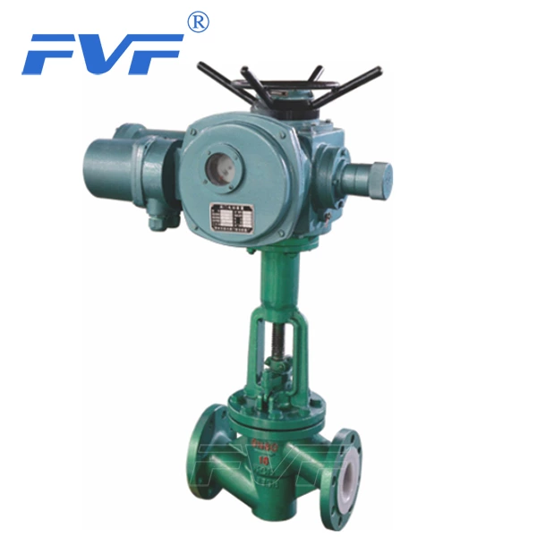
Fluorine-lined Stop Valve Manufacturer: Operation Specifications Of Stop Valves
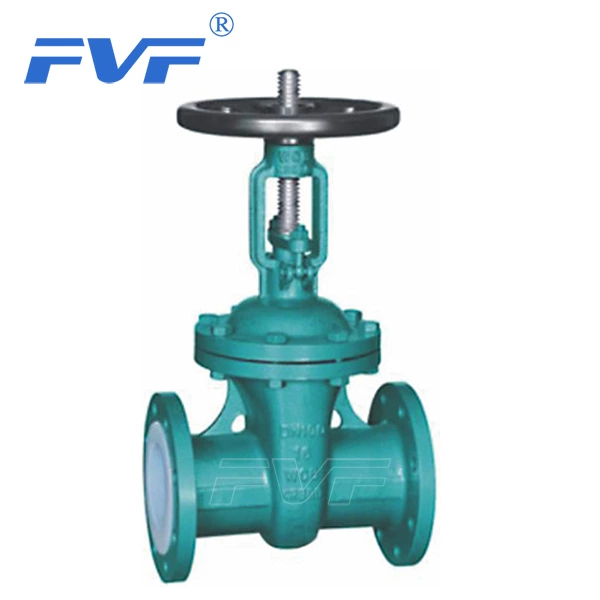
Most Lined Globe Valve choose T-shaped valve bodies, which can install the valve on straight-through pipelines. The fluid enters the center of the valve through the inlet (the valve core is in this position). The flow direction from here to 90° and then through the valve seat, and then 90° again to flow out of the valve.
The flow direction of the stop valve depends on the manufacturer or operator, but under most working conditions, the flow direction is almost always under the valve core. Putting the information in the flow direction, it has a constant resistance, but it is enough to overcome. For the flow under the valve core, the valve is relatively easy to close, and the fluid pressure and flow rate change is small. In addition, the flow under the valve core is easy to open because the fluid pushes the bottom of the valve core.
The manual stop valve can be adjusted to a percentage type, linear type or quick opening type flow characteristic. The flow characteristic determines the expected flow rate at a certain position of the valve (using the flow coefficient CV). In this way, for a certain flow characteristic, the user can determine the flow rate by the linear position of the manual handwheel. If the valve core head is in the throttling position (between fully open and fully closed), the flow will move towards the flow opening of the valve seat due to the pressure drop. In the throttle position, the valve plug head slightly extends into the seat ring, providing the corresponding flow at a special position for a given flow characteristic. When it returns and moves away from the valve seat, a larger flow can be achieved. If it extends further toward the valve seat, a smaller flow is formed. As the flow moves through the valve seat, the fluid pressure decreases and the velocity increases. After the flow enters the lower part of the globe valve, the flow area increases again, the pressure is restored, and the flow rate decreases.
When the flow enters the valve seat or valve plug area, an important design consideration is the workbench area of the valve body. Under reasonable conditions, the flow circulates freely along the valve plug and the valve seat, allowing the flow to enter the valve seat from all directions. If the workbench area is too narrow in any area (such as the back of the plug), the velocity may increase, causing noise and wear, or downstream turbulence. The valve plug head has different forces. If the valve plug head is not guided by the valve seat, it may cause slight scratches on the valve plug head.
When the globe valve is closed, the axial force of the handwheel acts on the plug. The force on the valve plug surface exerts pressure on the slight mismatch angle of the valve seat ring, not allowing any flow to pass through the closing element. In the fully open position, the entire seat area is open to flow.
The process flow is retained in the valve body and bonnet by the static seal of the end joint gasket if a flange or O-ring joint (RTJ) is used. The dynamic seal of the bonnet stuffing box prevents the flow from leaking through the plug sliding rod. Depending on the user's closing requirements, the flow can adjust the leakage of the closing element itself.