Fluorine-lined Diaphragm Valve Technical Information
1. Overview:
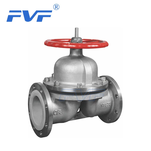
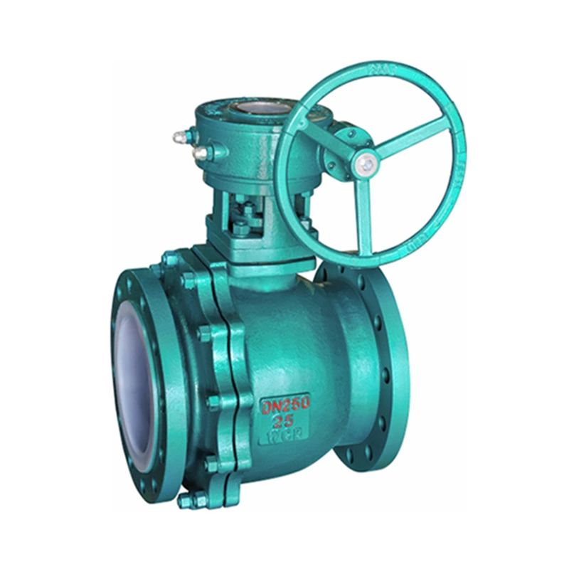
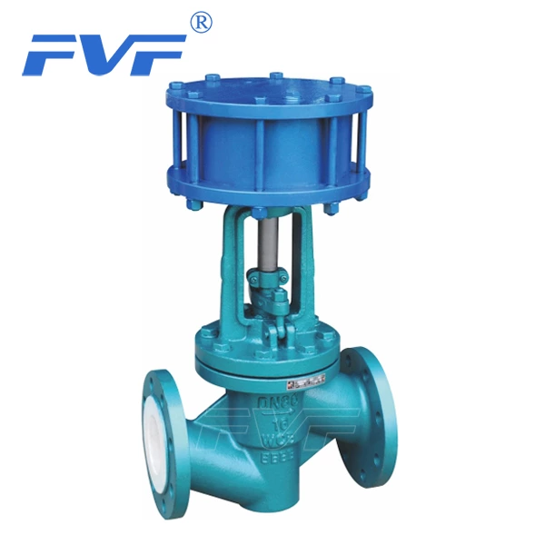
Lined Diaphragm Valve is a special type of valve with shutoff function. Its opening and closing parts are composed of a steel valve disc and a diaphragm made of soft material (rubber and fluoroplastic composite), and the inner cavity of the valve body is separated from the inner cavity of the valve cover to achieve the purpose of shutting off the medium in the pipe.
1. F4, F46, PVDF, PP, PO, PE lined diaphragm valve series recommended by Shangyu Group
The basic series of diaphragm valves are G41F4, G41F46, G41F2, G41PP, G41PO, G41PE weir type and G45F4, G45F46, G45F2, G45PP, G45PO, G45PE direct flow type.
2. Structural features:
(1). The composite diaphragm separates the lower inner cavity of the valve body from the inner cavity of the valve cover and forms a direct current channel with them, so that the valve stem, valve disc and other internal parts on the upper part of the diaphragm are completely isolated from the medium, eliminating the packing sealing structure, and avoiding both internal and external leakage of the medium.
(2). The diaphragm is made of FEP (Teflon) fluoroplastic and synthetic rubber, and customers can choose different lining materials according to the requirements of the medium to maximize economic benefits.
(3). The diaphragm as an actuator is prone to fatigue fracture due to frequent opening and closing, and should be replaced regularly depending on the working conditions and medium characteristics.
3. Valve manufacturing complies with the following standards:
a. Design and manufacturing are in accordance with GB 12239 standard;
b. Structural length is in accordance with GB 12221;
c. Flange size is in accordance with JB 78/JB 79 (GB.HG.SH) standard;
d. Pressure test is in accordance with JB/T 13927 standard;
e. Marking is in accordance with GB 12220 standard;
f. Supply is in accordance with JB/T 7928 standard.
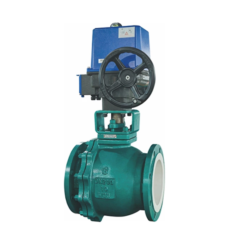
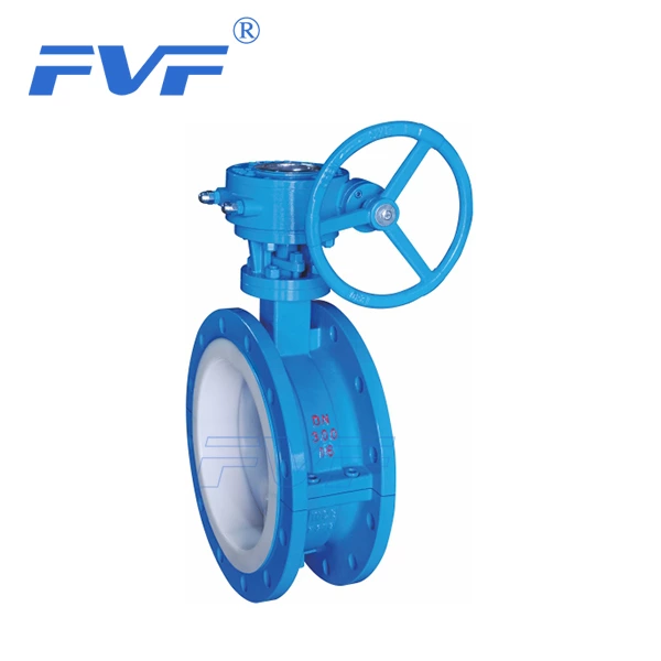
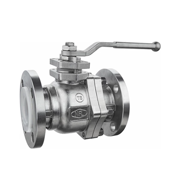
4. Drive mode
This product can be manufactured with handle, pneumatic, electric and other drive modes according to user needs.
5. Valve connection standard
This product can be manufactured and supplied in accordance with ANSI (American standard), DIN (German standard), JIS (Japanese standard) and other standards according to user needs.
2. Installation work:
1. Before installation, check whether the specifications and materials of the flanged ball valve are consistent with the design.
2. Before installation, clean up the sand, foreign matter and debris inside to avoid improper operation or leakage.
3. Before installation, the related piping should be properly suspended and fixed according to the regulations to avoid improper stress on the valve after installation.
4. Use flange piping:
(1) The two flange surfaces of the piping must be parallel and concentric.
(2) Gaskets must be installed between the valve and the flange during installation.
5. After the installation is completed, the full opening and full closing degrees should be confirmed again.
III. Operation:
1. Before starting the operation, use air spray to remove foreign objects on the piping, and clean the inside of the piping with clean water.
2. The operation of the switch is completely based on the marked direction.
3. When performing a piping pressure test, the valve should be opened.