Basic Structure And Working Principle Of Fluorine-lined Three-way Ball Valve
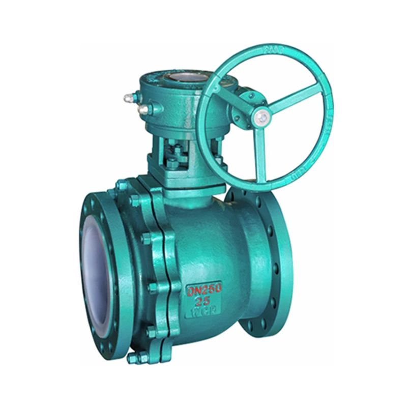
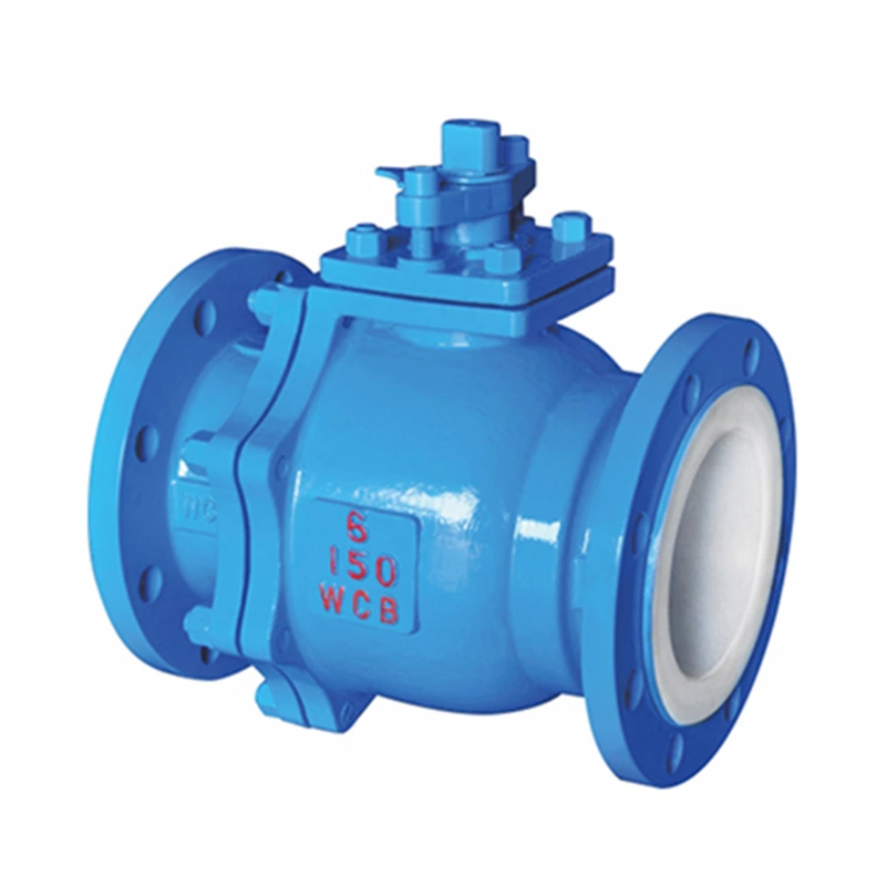
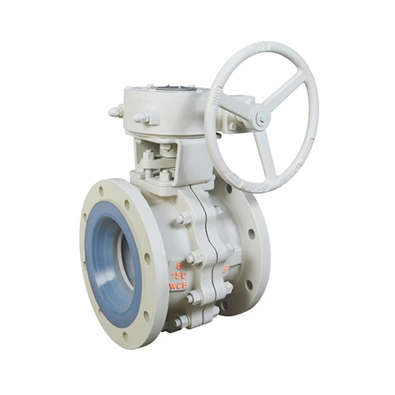
Lined Ball Valve is a special valve designed for highly corrosive media. It realizes the flow direction switching, diversion or confluence control of the fluid through the rotation of the ball. It is widely used in corrosive working environments such as chemical, pharmaceutical, and electroplating. Its core advantage lies in the use of fluoroplastic lining technology inside the valve body and key contact surfaces, which has excellent corrosion resistance and sealing reliability.
1. Basic structural composition
1. Valve body structure
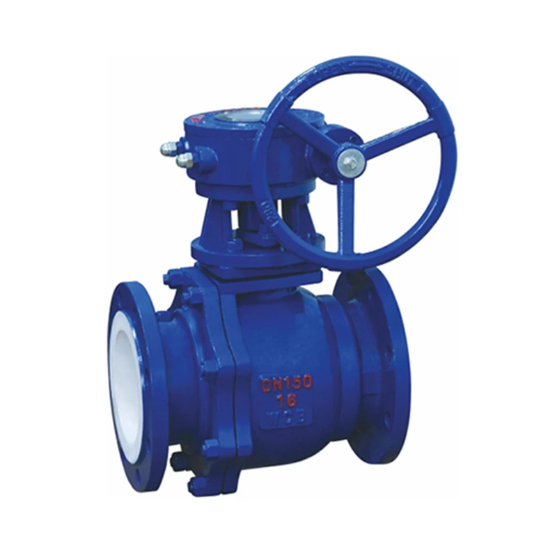
The valve body is made of casting or forging technology, and the inner wall and the flow channel surface in contact with the medium are evenly lined with fluoroplastics (such as PTFE, F46, PFA) to form a corrosion-resistant barrier. The lining thickness is usually 2~3mm to ensure long-term anti-permeability.
2. Flow channel type
* L-shaped tee (Q44F46 type): The inlet and outlet channels are distributed at right angles, the ball channel is L-shaped, and the flow direction switching between two vertical pipelines (such as A→B or A→C) is achieved by 90° rotation.
* T-shaped tee (Q45F46 type): The flow channel is distributed in a T shape, and the ball channel is a tee structure. The medium can be divided, merged or switched in multiple directions (such as A→B+C, B→A+C, etc.) by rotating 90° or 180°.
3. Sealing components
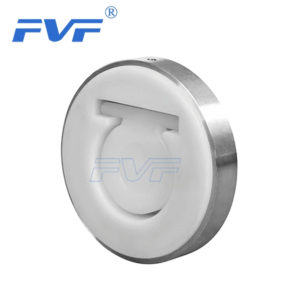
* Elastic lip seal seat: Made of fluoroplastic or reinforced composite material, with a "lip-shaped" edge design. Under the pressure of the medium, the sealing lip is close to the surface of the ball to form a self-tightening seal, which can compensate for the deformation caused by temperature changes.
* Ball: The surface is coated with a fluoroplastic layer or the whole is made of corrosion-resistant alloy, and the precision is polished to Ra≤0.8μm to ensure low friction with the sealing seat.
4. Drive device
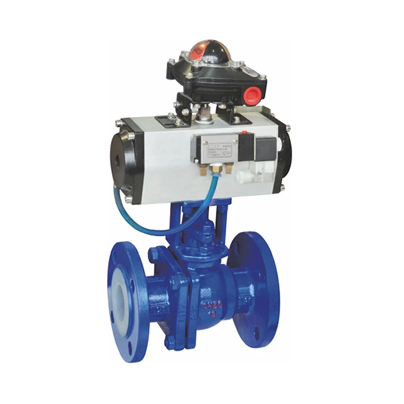
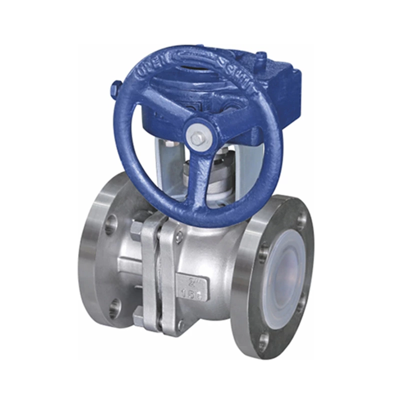
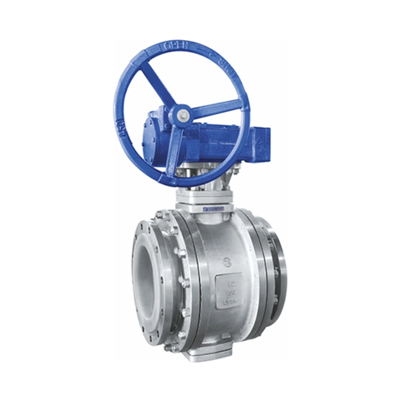
Supports manual (handle/worm gear), pneumatic or electric operation, and a packing seal structure is used between the valve stem and the valve body to prevent leakage of the medium.
2. Working principle
1. Flow control mechanism
The valve stem is driven to rotate by the drive device, so that the ball rotates around the axis. The relative position change between the flow channel inside the ball and the flow channel of the valve body determines the flow path of the medium:
* L-shaped valve: The ball rotates 90° to switch the inlet and outlet flow direction, which is suitable for two-way alternating operation (such as switching between feeding and emptying of the reactor).
* T-shaped valve: The ball rotates 90° or 180° to achieve the confluence, diversion or cutoff of three-way media (such as multi-tank parallel circulation system).
2. Sealing principle of fluorine-lined three-way ball valve
* Low-pressure working condition: The initial seal is achieved by relying on the pre-tightening force of the sealing seat and the interference fit of the ball.
* High-pressure working condition: The medium pressure pushes the lip of the sealing seat to close to the ball. The higher the pressure, the stronger the sealing effect (self-sealing effect).
* Temperature difference compensation: The fluoroplastic sealing seat has elastic memory characteristics and can adapt to temperature fluctuations of -50℃~200℃ to avoid leakage caused by thermal expansion and contraction.
The above is an introduction to the basic structure and working principle of the fluorine-lined three-way ball valve. At present, this valve is widely used in chemical processes, environmental protection projects, electroplating equipment, pharmaceuticals and other industries.
