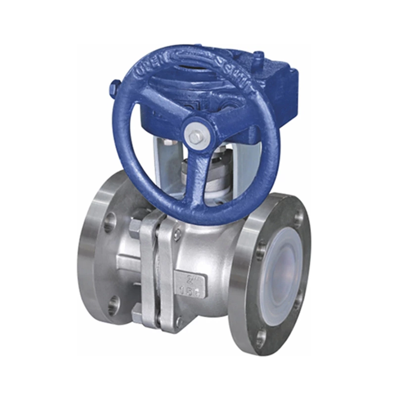
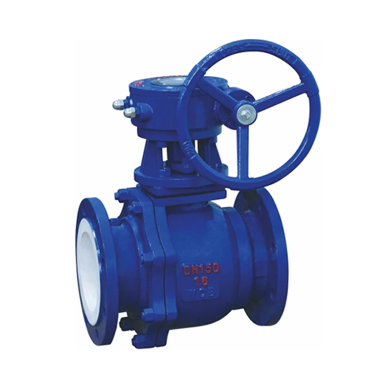
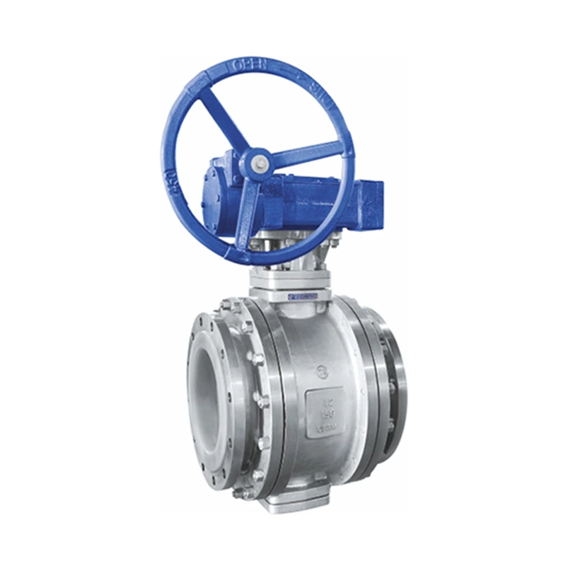
Application And Classification Of Fluorine-lined Stop Valves
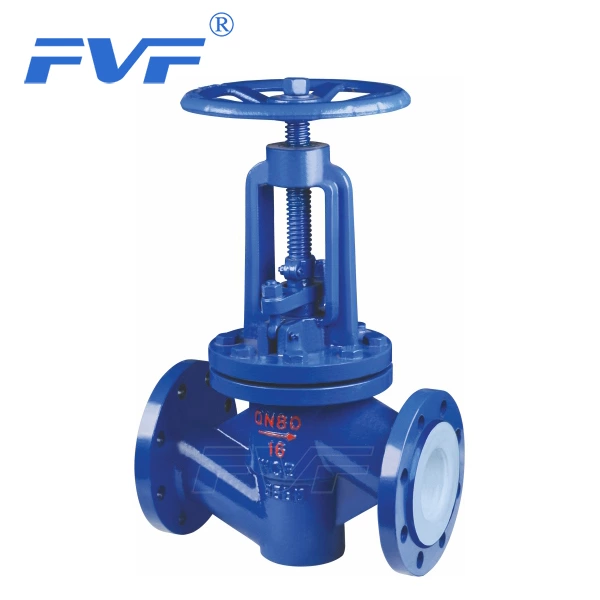
Lined Globe Valve refers to the valve with the closing part (valve disc) along the center line of the valve seat. It mainly plays a cutting role on the pipeline.
Fluorine-lined stop valves are very common, but due to the large opening and closing torque and long mechanism, the nominal size is usually limited to DN250 or less. In addition, the nominal diameter of the stop valve is also related to the working pressure.
The obvious advantages of the stop valve are as follows: |
1. During the opening and closing process, the friction between the valve disc and the sealing surface of the valve body is smaller than that of the gate valve, so it wears.
2. The opening height is much smaller than that of the gate valve.
3. Usually there is only one sealing surface on the valve body and the valve disc, so the manufacturing process is better and easy to maintain.
However, the shortcomings of the stop valve cannot be ignored. Its shortcomings are mainly caused by the shape of the body cavity. In the body cavity, the medium changes from a straight line direction to an upward flow, thus causing pressure loss, especially in hydraulic devices, this pressure loss is particularly obvious.
There are many types of stop valves, which are generally classified according to the position of the thread on the valve stem, the channel form, and the shape of the valve disc. It can be mainly divided into:
1. Upper threaded stem stop valve
This type of stop valve is widely used. Its stem thread is outside the shell and is not in direct contact with the working medium. This prevents the stem from being corroded by the medium, and is also easy to lubricate and labor-saving to operate.
2. Lower threaded stem stop valve
The stem thread of this stop valve is in the valve body and in direct contact with the medium. It is not only unable to be lubricated, but also susceptible to medium erosion.
This type of stop valve is mostly used in places with relatively small nominal sizes and low working temperatures of the medium.
3. Straight-through stop valve
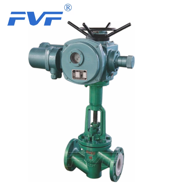
The two inlet channels of the medium are in the same direction and are 180°, as shown in Figures 2-38 and 2-39. This type of stop valve makes the degree of destruction of the flow state relatively small, so the pressure loss through the valve is also reduced accordingly.
4. Angle stop valve
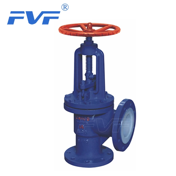
The inlet channels of the angle stop valve are not in the same direction and form a true angle of 90°, as shown in Figure 2-40. This type of stop valve changes the flow direction of the medium passing through the valve, so it will produce a certain pressure drop. The biggest advantage of the angle stop valve is that the valve can be installed at the corner of the pipeline system, which not only saves 90° elbows but also facilitates operation. This type of valve is widely used in the synthetic ammonia production system and refrigeration system of fertilizer plants.
5. Three-way stop valve
A stop valve with three channels is usually used to change the flow direction of the medium and distribute the medium.
6. Direct current stop valve
The valve stem and channel of the direct current stop valve are at an angle, and its valve seat cover is at a certain angle to the inlet channel; the valve body can be made into an integral type or a separate type, as shown in Figure 2-42. The stop valve with a separate valve body uses two valve bodies to clamp the valve seat in the middle, which is easy to manufacture and easy to maintain. This type of stop valve makes the fluid almost unchanged in flow direction and has the smallest flow resistance among stop valves; its installation method is close to the straight-through type, but special attention should be paid to facilitate operation after the pipeline is installed.
7. Plunger stop valve
The plunger stop valve is a deformation of the conventional stop valve. In the plunger stop valve, the valve disc and valve seat are designed according to the principle of the plunger; the valve disc is designed as a plunger valve, and the valve seat is designed as a sleeve ring, and the sealing is achieved by the cooperation of the plunger valve and the sleeve ring. This valve is simple to manufacture, and the sleeve ring can be made of graphite and polytetrafluoroethylene; it has good sealing performance and can be used for high and low temperature media. The valve is mainly used for opening and closing, but the plunger and sleeve ring designed in a special form can also be used for flow regulation.
8. Needle stop valve
The needle stop valve is used for precise flow control, usually limited to small diameters, and the size of the valve seat hole is generally smaller than the nominal size.
